By stinkwheel - Thu Dec 30, 2021 8:09 pm
- Thu Dec 30, 2021 8:09 pm
#99535
This is a copy of a build blog post I made on another forum. The language is probably a tad "younger" than many are used to on here. I'm not saying everything I did is correct but people might find the pictures handy if nothing else.
Ok. Stripping an albion 4-speed gearbox. These gearboxes are a 1940's design and weren't regarded as particularly pleasant to use even then. What they lack in finesse, they don't really make up for in functionality. I'd say they are the second worst gearbox I have ever used, the worst being the one fitted to an Estonian home market Ural.
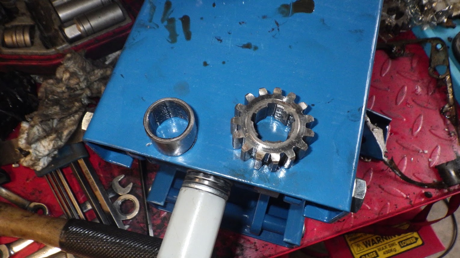
One thing you can do however is piss about with them. i'm going in to change out two of the gears which will radically alter the gearing for trials use.
Standard ratios: 1st = 2.78:1, 2nd = 1.84:1, 3rd = 1.36:1, 4th = 1:1.
New ratios: 1st = 3.19:1, 2nd = 1.97:1, 3rd = 1.46:1, 4th = 1:1.
You'll notice 4th remains the same because it's straight through. So I'll land up with three super low gears then an enormous gap to 4th which will be road speed, because it's geared down 2 teeth on the front, it should pull 4th in most road conditions and sit at 50-ish. if it won't, I'll be stuck doing 30mph until the hill flattens out.
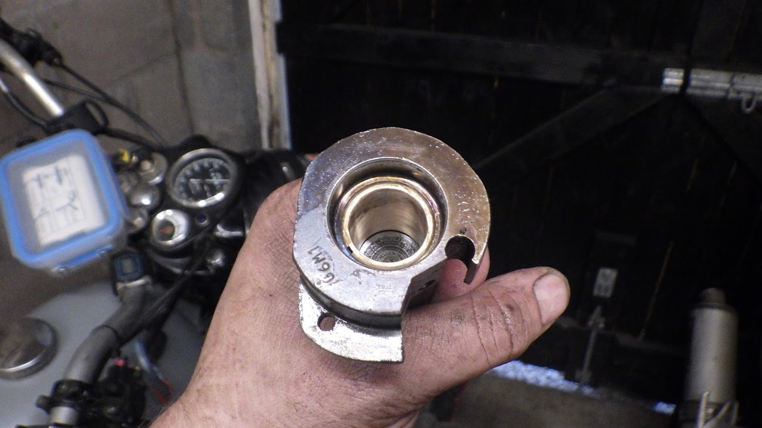
The other thing I want to do is fit a bronze bush on the layshaft because the cast iron one is picking up when I give it some wells and swinging the kickstart down (I'll explain this when i get to it).
Lots of detail because someone requested it.
First remove the kickstart, gear lever and neutral finder lever. It helps to put it in gear first for reasons which will become clear later.

Undo the slotted screws, remembering that the top "keyhole cover" screw also holds the gearbox cover on.
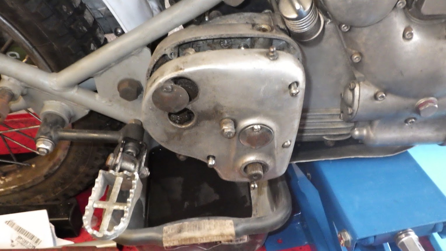
Unhook the clutch cable and lift the cover off.


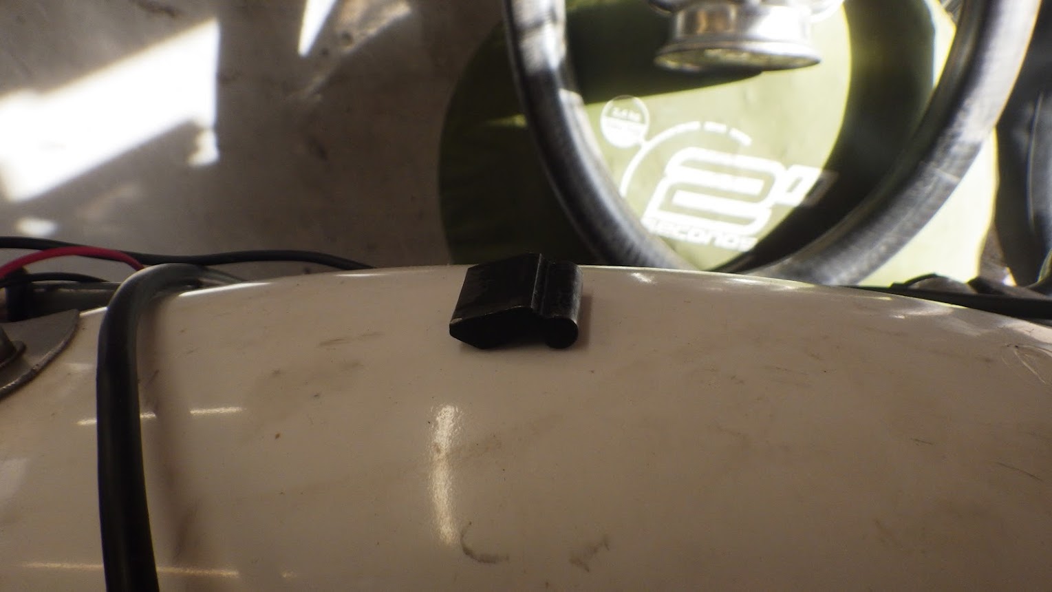
Undo the two half nuts holding the stop-plate on and remove it. This will expose the ratchet assembly.
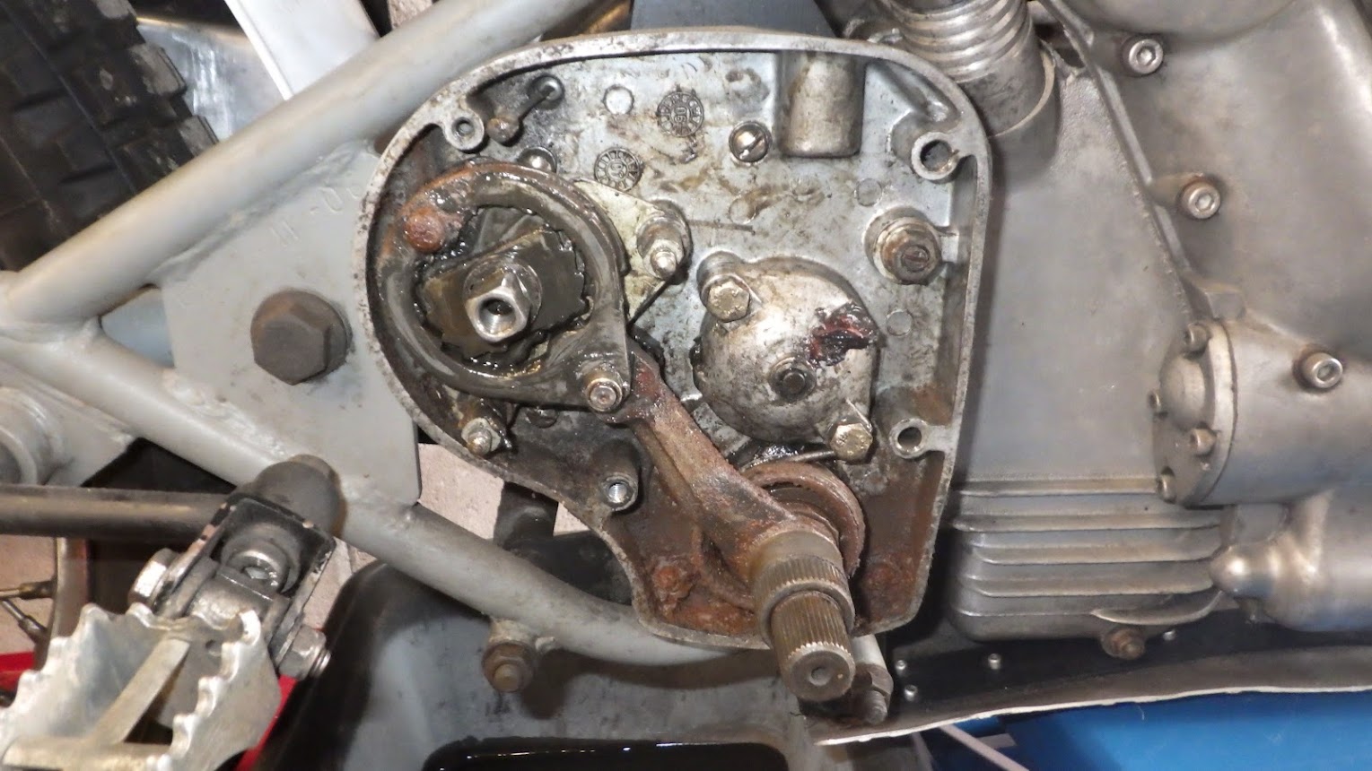
The whole ratchet assembly lifts off. As does the foot control lever.

The gear operator selector assembly locknut (hex nut at the top right) needs to be removed.
The bottom bolt on the ball bearing cap also retains the kickstart return spring, once undone the spring can be removed. Try to support this bolt in position when undoing using a socket. As it nears being undone, the spring can rock the last coule of threads out, damaging the alloy.

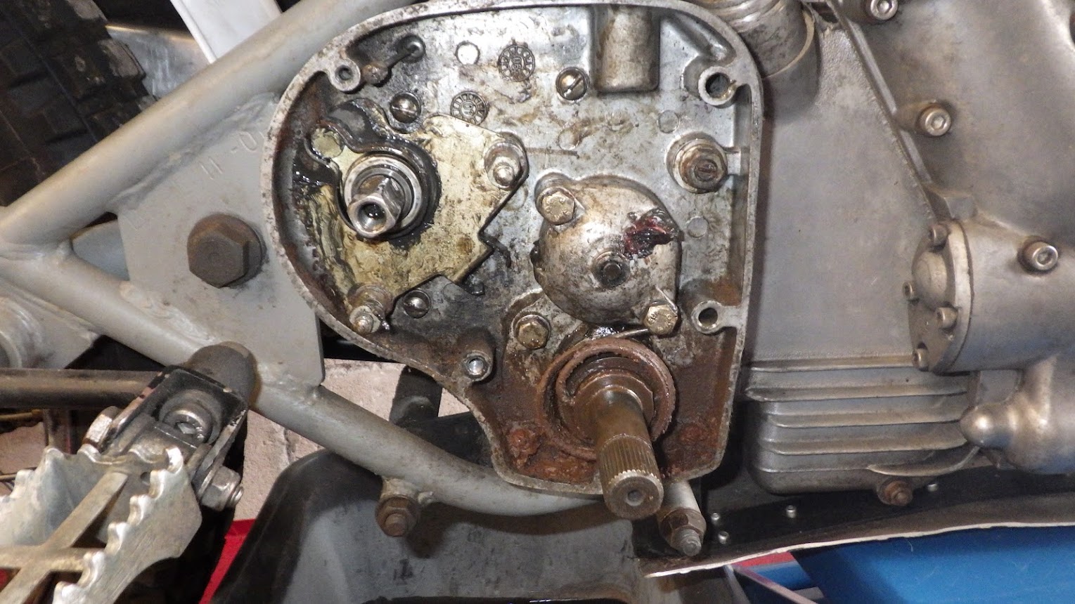
The two pins holding the adjuster plate on have two flats on which can be undone and the plate lifted off with its springs in-situ.

The final bearing cap nut can be removed and the bearing cap tapped loose. You can also pull the clutch pushrod out which runs through the centre of the hollow mainshaft. There may be a ball bearing stuck to the end, don't lose it!
This exposes the mainshaft nut which has a tabbed washer. THIS NUT IS A REVERSE THREAD. This is why you put the bike in gear before. You can hold the back wheel with one hand and undo this nut with the other. If it's in neutral, the shaft will just spin. If you need to put the bike in gear now, you can rotate the square shaft with a spanner as you are turning the engine and you should get a gear.

The bearing is not sealed. This is why these gearboxes are grease and not oil filled. Now undo the 5 slot head screws (there are two under all that nasty yak at the bottom).
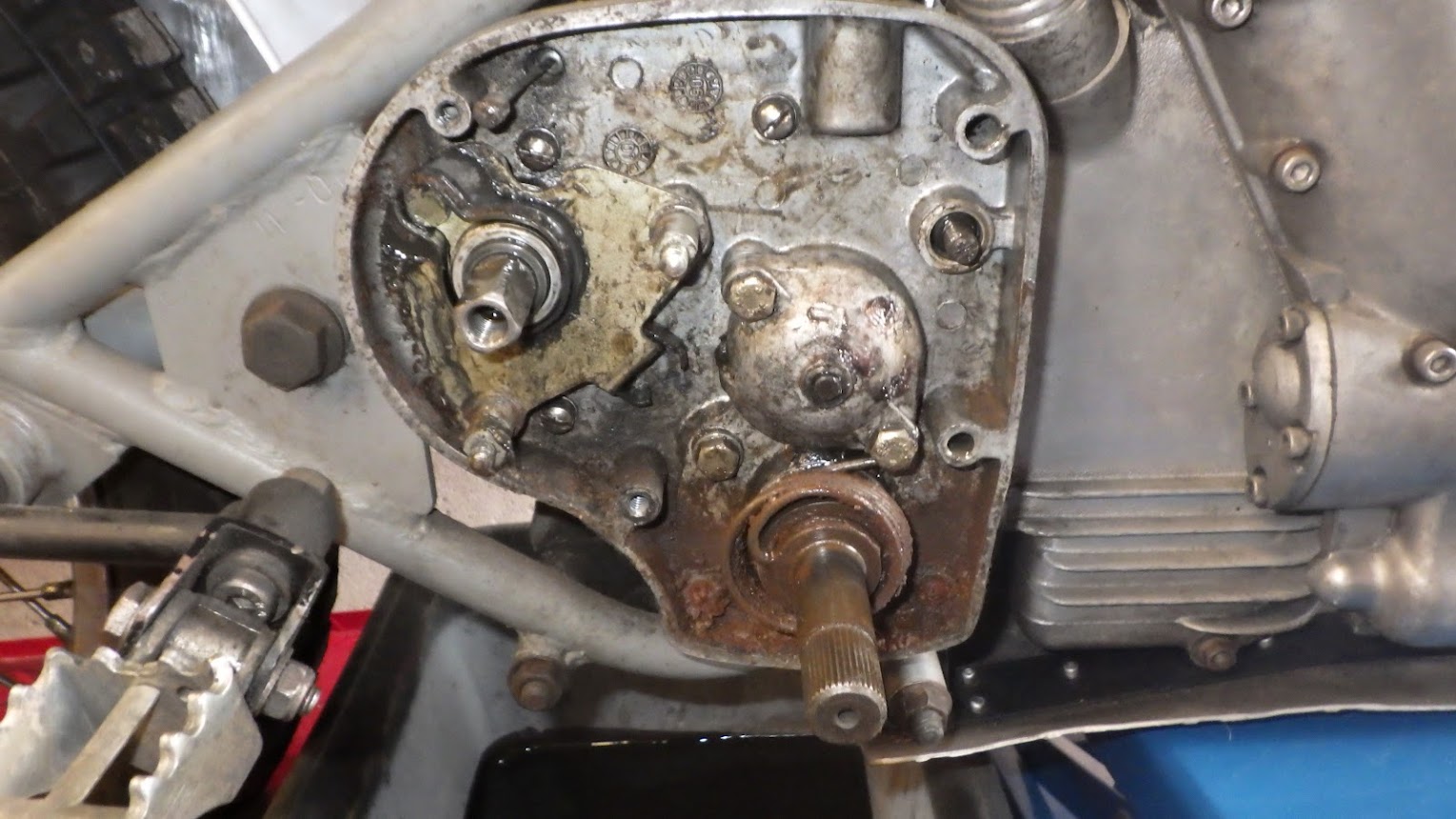
Do not remove the hex-bolt at the 10 o' clock position to the kickstart shaft like I did here. It holds a crescent-shaped detent for the kickstart pawl in place and it is a real fiddle to get in the proper position.

The whole outer cover should now lift off, taking the kickstart shaft with it. This is the inside view.
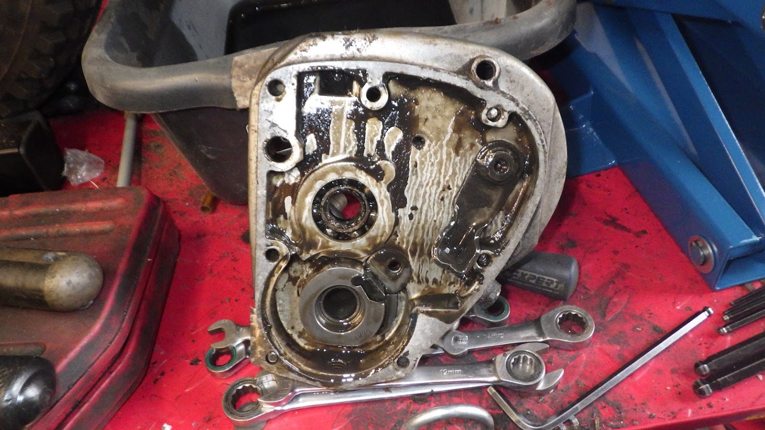
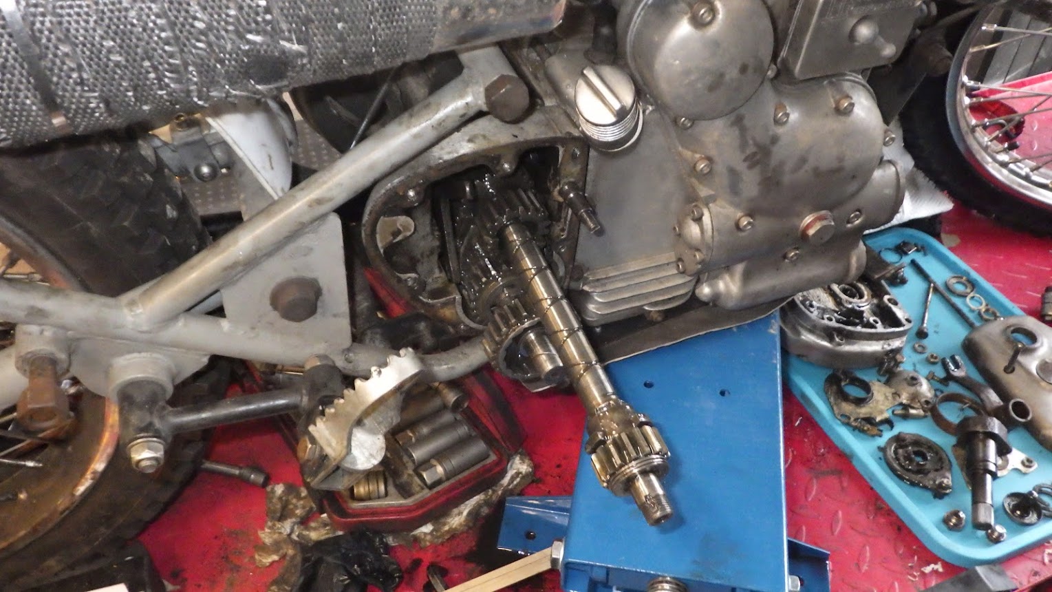
And the inside of the gearbox is now in sight.
One more thing that can be done from this side is to remove the gear operator pin bush. It's on the back of the gearbox, facing the rear wheel. It's a total sod to remove because while it's slotted, it has the end of the shaft protruding out of the middle. Idealy you'd need a huge flat screwdriver with a notch in the middle. I may well make a tool for this before reassembly. It's also really hard to reach.
Once the bush is undone, the pin can be removed which frees up the selector forks inside the gearbox.
On reassembly, it became apparent that it was not necessary to remove this pin! Once the mainshaft has been removed and the layshaft pulled back out of the left hand bushing, there is enough play to lift the gear operator off the forks and slide the gear clusters out. It is a fiddle but do-able.

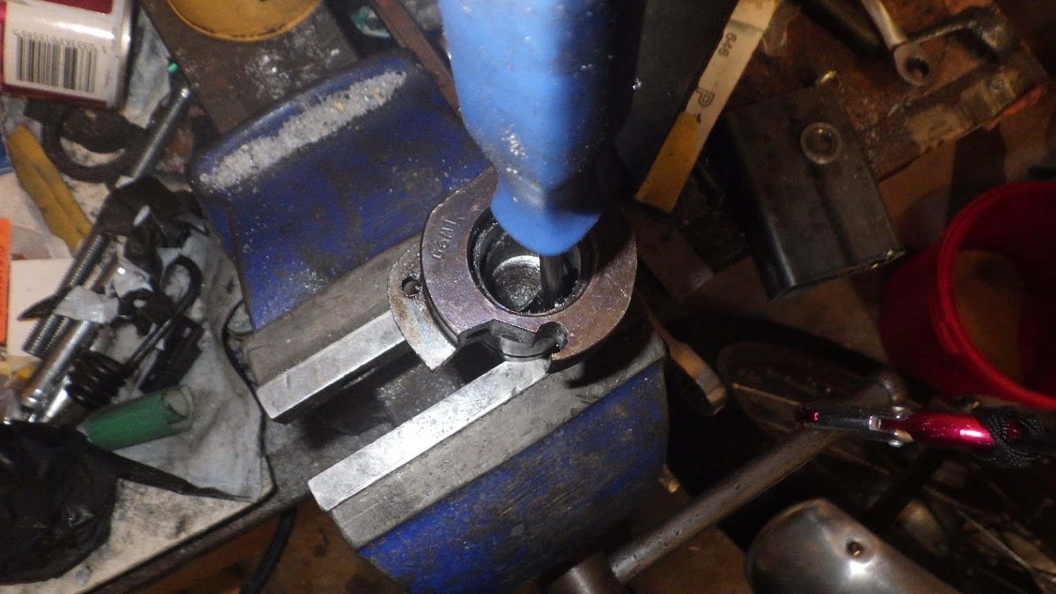
Further dissasembly requires removal of the primary chaincase. A job for tomorrow I think because I spent most of the rest of the day getting the old layshaft bushing out.
Ok. Stripping an albion 4-speed gearbox. These gearboxes are a 1940's design and weren't regarded as particularly pleasant to use even then. What they lack in finesse, they don't really make up for in functionality. I'd say they are the second worst gearbox I have ever used, the worst being the one fitted to an Estonian home market Ural.
One thing you can do however is piss about with them. i'm going in to change out two of the gears which will radically alter the gearing for trials use.
Standard ratios: 1st = 2.78:1, 2nd = 1.84:1, 3rd = 1.36:1, 4th = 1:1.
New ratios: 1st = 3.19:1, 2nd = 1.97:1, 3rd = 1.46:1, 4th = 1:1.
You'll notice 4th remains the same because it's straight through. So I'll land up with three super low gears then an enormous gap to 4th which will be road speed, because it's geared down 2 teeth on the front, it should pull 4th in most road conditions and sit at 50-ish. if it won't, I'll be stuck doing 30mph until the hill flattens out.
The other thing I want to do is fit a bronze bush on the layshaft because the cast iron one is picking up when I give it some wells and swinging the kickstart down (I'll explain this when i get to it).
Lots of detail because someone requested it.
First remove the kickstart, gear lever and neutral finder lever. It helps to put it in gear first for reasons which will become clear later.
Undo the slotted screws, remembering that the top "keyhole cover" screw also holds the gearbox cover on.
Unhook the clutch cable and lift the cover off.
Undo the two half nuts holding the stop-plate on and remove it. This will expose the ratchet assembly.
The whole ratchet assembly lifts off. As does the foot control lever.
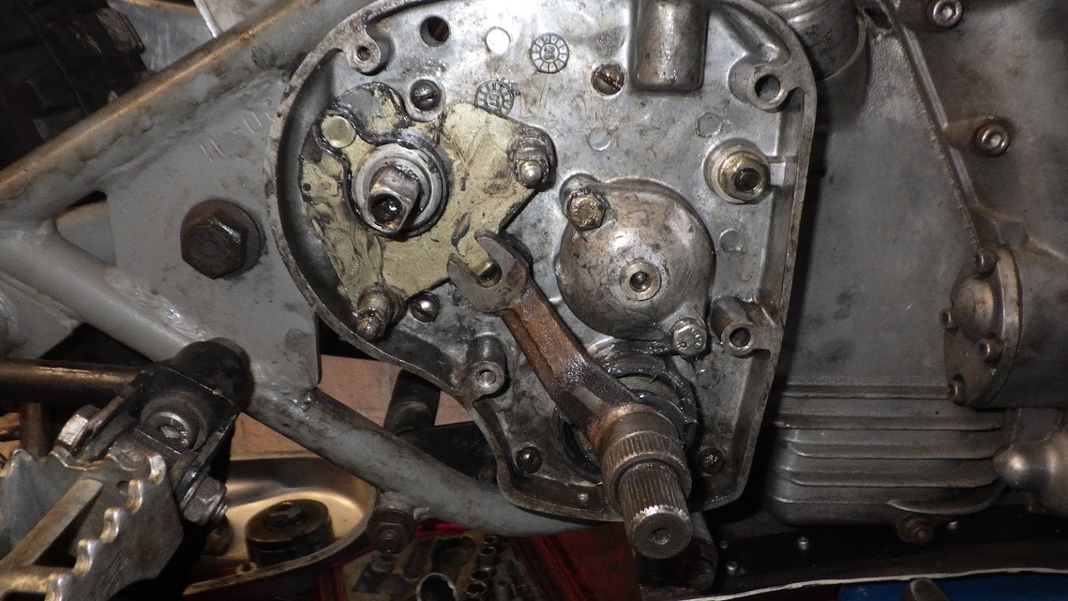
The gear operator selector assembly locknut (hex nut at the top right) needs to be removed.
The bottom bolt on the ball bearing cap also retains the kickstart return spring, once undone the spring can be removed. Try to support this bolt in position when undoing using a socket. As it nears being undone, the spring can rock the last coule of threads out, damaging the alloy.
The two pins holding the adjuster plate on have two flats on which can be undone and the plate lifted off with its springs in-situ.
The final bearing cap nut can be removed and the bearing cap tapped loose. You can also pull the clutch pushrod out which runs through the centre of the hollow mainshaft. There may be a ball bearing stuck to the end, don't lose it!
This exposes the mainshaft nut which has a tabbed washer. THIS NUT IS A REVERSE THREAD. This is why you put the bike in gear before. You can hold the back wheel with one hand and undo this nut with the other. If it's in neutral, the shaft will just spin. If you need to put the bike in gear now, you can rotate the square shaft with a spanner as you are turning the engine and you should get a gear.
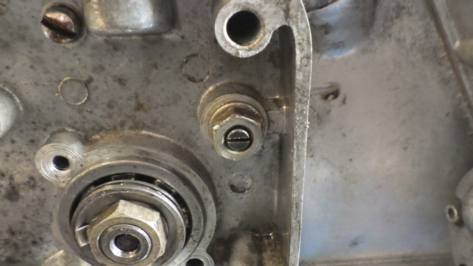
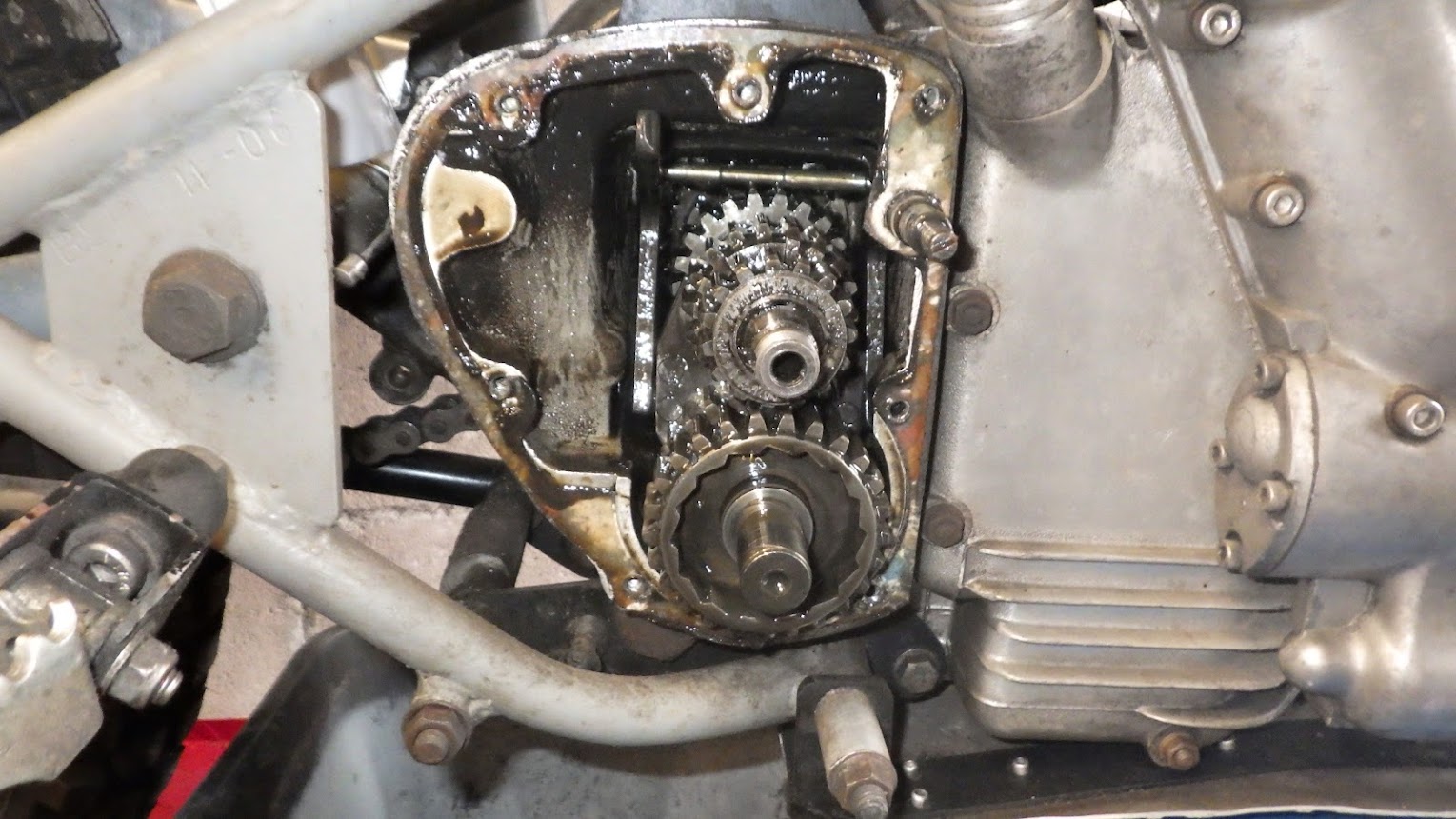
The bearing is not sealed. This is why these gearboxes are grease and not oil filled. Now undo the 5 slot head screws (there are two under all that nasty yak at the bottom).
Do not remove the hex-bolt at the 10 o' clock position to the kickstart shaft like I did here. It holds a crescent-shaped detent for the kickstart pawl in place and it is a real fiddle to get in the proper position.
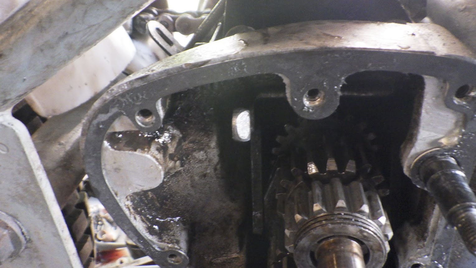
The whole outer cover should now lift off, taking the kickstart shaft with it. This is the inside view.
And the inside of the gearbox is now in sight.
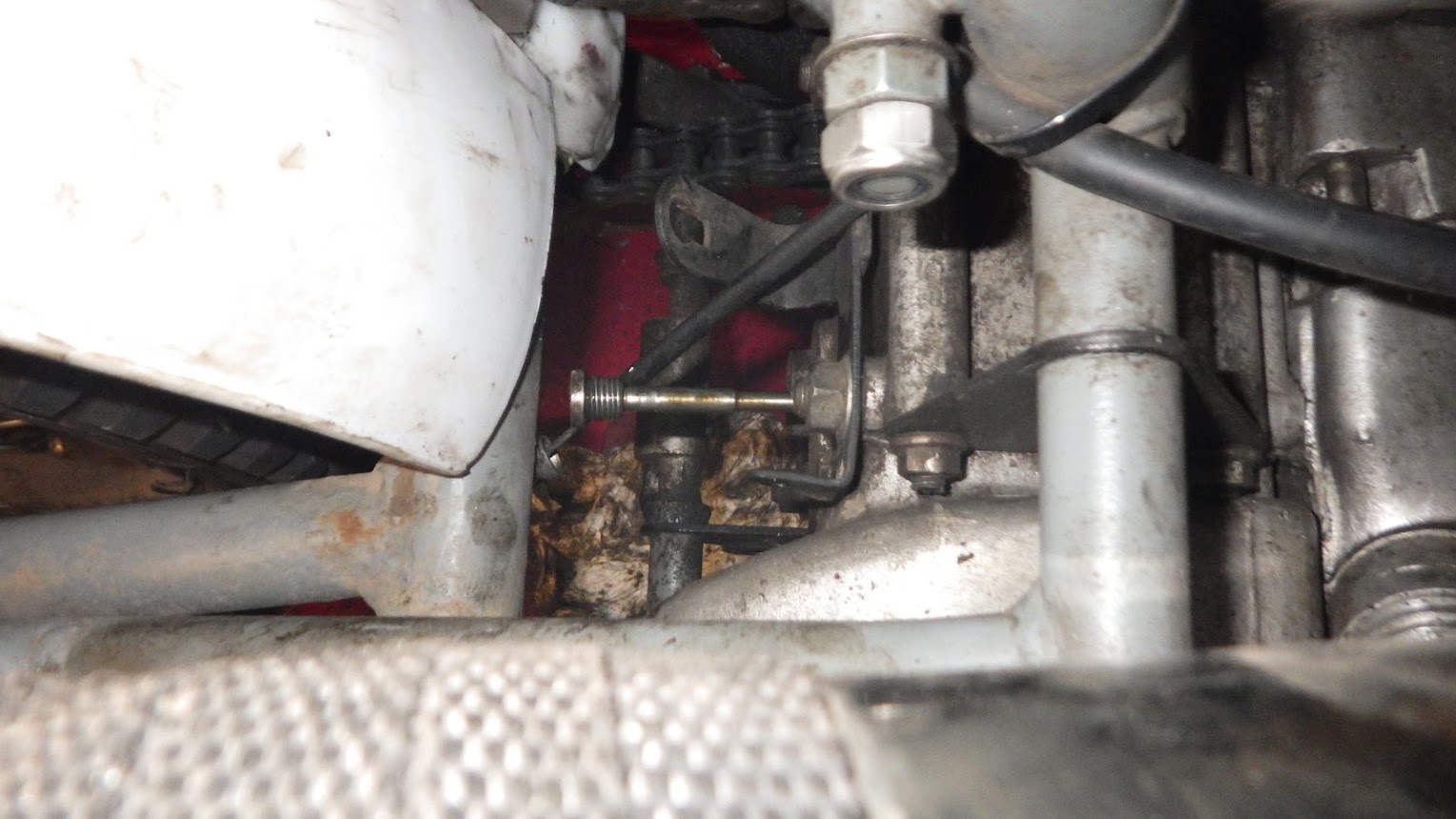
One more thing that can be done from this side is to remove the gear operator pin bush. It's on the back of the gearbox, facing the rear wheel. It's a total sod to remove because while it's slotted, it has the end of the shaft protruding out of the middle. Idealy you'd need a huge flat screwdriver with a notch in the middle. I may well make a tool for this before reassembly. It's also really hard to reach.
Once the bush is undone, the pin can be removed which frees up the selector forks inside the gearbox.
On reassembly, it became apparent that it was not necessary to remove this pin! Once the mainshaft has been removed and the layshaft pulled back out of the left hand bushing, there is enough play to lift the gear operator off the forks and slide the gear clusters out. It is a fiddle but do-able.
Further dissasembly requires removal of the primary chaincase. A job for tomorrow I think because I spent most of the rest of the day getting the old layshaft bushing out.